cnc drawing machine report Creating accurate technical drawings for CNC machining requires precision, attention to detail, and manufacturing process knowledge. Here are some steps to follow: Create accurate technical drawings by extracting the . The online metal weight calculator allows you to calculate the weight of common metals, such as mild steel, carbon steel, stainless steel, aluminum alloy, copper, brass, etc.; Metal shapes include metal plate, metal sheet, metal bar, round tube, square pipe, hollow, angle bar, T-bar, H/I/W beam, U/C channel, profile and other common metal products.
0 · technical drawing for cnc
1 · engineering drawing for cnc manufacturing
2 · drawing for cnc parts
3 · cnc machining drawings
4 · cnc drawings
5 · cnc drawing process
Welding a corner joint secures two metal pieces at a 90-degree angle. This guide will teach you the various types of corner joints and tips for each project type.

technical drawing for cnc
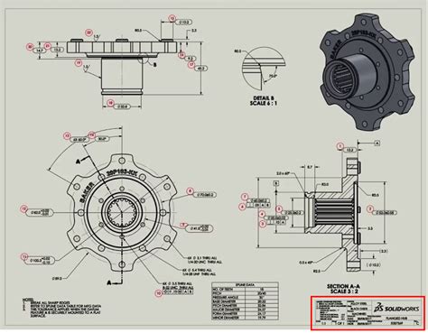
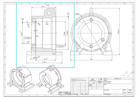
This guide delves into the basics of machining drawings, their importance, and the essential elements of a CNC machining drawing. You will also learn why you need to prepare a technical drawing when sourcing parts . A technical drawing for CNC Machining is an essential part to build a 3d part by CNC machining. It provides a detailed representation of the part or product that needs to be machined, allowing manufacturers to accurately . Technical drawings are the instructions that tell a CNC machinist how to make a part. They can be created using CAD software, or they can be hand-drawn. Once the technical drawing is complete, it is saved as a PDF and .A research on CNC machine system named ‘A New Developed Technique for Handwriting .
Creating accurate technical drawings for CNC machining requires precision, attention to detail, and manufacturing process knowledge. Here are some steps to follow: Create accurate technical drawings by extracting the . This article sums up all the specifications you need to take into account when preparing a technical drawing for any CNC machining project, and details the 10 steps to follow in order to get a flawless design.In this article, we’ll explain when to include a technical drawing (or machining blueprints) in your CNC order and what you need to include to get the most out of part sourcing. This article also includes technical drawing guidelines and best .
The paper presents an approach to design user friendly and fluid movements of a CNC .An intricate diagram or picture that details the dimensions, tolerances, and other details required for a CNC machine to make a particular item or product is referred to as a technical drawing in CNC. This guide delves into the basics of machining drawings, their importance, and the essential elements of a CNC machining drawing. You will also learn why you need to prepare a technical drawing when sourcing parts and the importance of . In this guide, I will walk you through the process of creating technical drawings for CNC machining projects, from start to finish. I will cover everything from the basics of drawing software to more advanced techniques such as 3D rendering.
A technical drawing for CNC Machining is an essential part to build a 3d part by CNC machining. It provides a detailed representation of the part or product that needs to be machined, allowing manufacturers to accurately produce the desired outcome. Technical drawings are the instructions that tell a CNC machinist how to make a part. They can be created using CAD software, or they can be hand-drawn. Once the technical drawing is complete, it is saved as a PDF and sent to the CNC machine .A research on CNC machine system named ‘A New Developed Technique for Handwriting Robot’ presented by Nur Shazwany Zamani, M.N. Mohammed [3] are the authors who have generated cheap handwriting robot which is based on the fundamental of CNC.
Creating accurate technical drawings for CNC machining requires precision, attention to detail, and manufacturing process knowledge. Here are some steps to follow: Create accurate technical drawings by extracting the dimensions, tolerances, and . This article sums up all the specifications you need to take into account when preparing a technical drawing for any CNC machining project, and details the 10 steps to follow in order to get a flawless design.
In this article, we’ll explain when to include a technical drawing (or machining blueprints) in your CNC order and what you need to include to get the most out of part sourcing. This article also includes technical drawing guidelines and best practices from our engineers.
The paper presents an approach to design user friendly and fluid movements of a CNC machine to perform writing tasks. The design of proposed writing machine comprises both hardware and software. In this project the concept of converting textual matter into G-code is implemented.

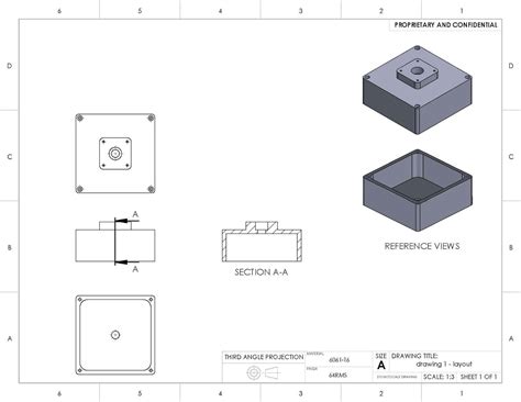
An intricate diagram or picture that details the dimensions, tolerances, and other details required for a CNC machine to make a particular item or product is referred to as a technical drawing in CNC.
This guide delves into the basics of machining drawings, their importance, and the essential elements of a CNC machining drawing. You will also learn why you need to prepare a technical drawing when sourcing parts and the importance of . In this guide, I will walk you through the process of creating technical drawings for CNC machining projects, from start to finish. I will cover everything from the basics of drawing software to more advanced techniques such as 3D rendering. A technical drawing for CNC Machining is an essential part to build a 3d part by CNC machining. It provides a detailed representation of the part or product that needs to be machined, allowing manufacturers to accurately produce the desired outcome. Technical drawings are the instructions that tell a CNC machinist how to make a part. They can be created using CAD software, or they can be hand-drawn. Once the technical drawing is complete, it is saved as a PDF and sent to the CNC machine .
A research on CNC machine system named ‘A New Developed Technique for Handwriting Robot’ presented by Nur Shazwany Zamani, M.N. Mohammed [3] are the authors who have generated cheap handwriting robot which is based on the fundamental of CNC.
engineering drawing for cnc manufacturing
Creating accurate technical drawings for CNC machining requires precision, attention to detail, and manufacturing process knowledge. Here are some steps to follow: Create accurate technical drawings by extracting the dimensions, tolerances, and . This article sums up all the specifications you need to take into account when preparing a technical drawing for any CNC machining project, and details the 10 steps to follow in order to get a flawless design.
In this article, we’ll explain when to include a technical drawing (or machining blueprints) in your CNC order and what you need to include to get the most out of part sourcing. This article also includes technical drawing guidelines and best practices from our engineers.The paper presents an approach to design user friendly and fluid movements of a CNC machine to perform writing tasks. The design of proposed writing machine comprises both hardware and software. In this project the concept of converting textual matter into G-code is implemented.

drainage junction box pump
The weights of the contents of a cereal box are normally distributed with a mean weight of 20 ounces and standard deviation is 0.07 ounce. Boxes in the lower 5% do not meet the minimum .
cnc drawing machine report|cnc machining drawings