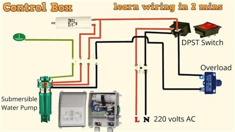
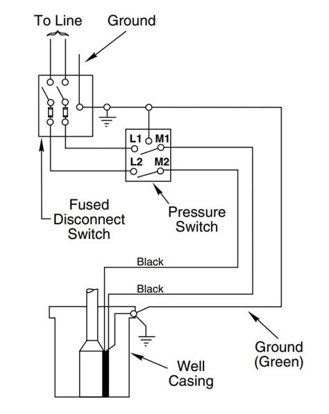
electrical connection box for 2 wire pump The wiring diagram for a single phase water well pump outlines the connections and electrical components required to operate the pump effectively. It typically includes the power source, control box, pressure switch, and pump motor. You need an extender, something that extends out the entire box. The ones you show will work but for things like backspashes and the like this is more commonly used: http://www.aifittings.com/catalog/miscellaneous/box-extenders/BE1
0 · well pump wiring size
1 · submersible well pump wiring diagram
2 · submersible water pump wiring diagram
3 · how to wire a well pump
4 · how to wire a pump
5 · 3 wire well pump installation
6 · 2 wire well pump wiring
7 · 2 wire pump wiring diagram
Electrical boxes are an essential part of any home electrical system. There are several types of electrical boxes, and they all house wiring connections, the parts of your electrical system where wires join an outlet, switch, or even other wires.
When it comes to wiring a 2 wire well pump, there are a few key components to consider. The power supply typically consists of a two-wire electrical cable that connects to the control box. The control box is then connected to the pump . What is a 2-Wire Submersible Well Pump Wiring Diagram? A 2-wire submersible well pump wiring diagram is a simplified representation of the electrical connections between . Well pump wiring diagrams, 3-wire, 4-wire, Install or detect & fix well pump control box & wiring for 2-wire, 3-wire & 4-wire pump installations. POST a QUESTION or COMMENT .The wiring diagram for a single phase water well pump outlines the connections and electrical components required to operate the pump effectively. It typically includes the power source, control box, pressure switch, and pump motor.
By following the connection establishing process, you can easily connect the wire of a submersible pump. After establishing the connection, you should re-check the entire wiring diagram to ensure everything is correctly .In this article, we will explore the basics of a well pump wiring schematic and discuss the important components and connections involved. A well pump wiring schematic typically consists of several components, including the pump motor, .
After properly sizing the wires and determining the appropriate cable size, the next step in wiring a well pump is to install the junction box and well pump control box. These boxes serve as important connections points and provide a safe .The wiring diagram for a 220V well pump provides a visual representation of the electrical connections required for the pump to function correctly. It outlines how the different components, such as the motor, control box, pressure switch, and . If you’re not wiring from a breaker but rather to a generator, the wiring can go straight to the pressure switch or starter box L1 and L2. You will need to cap the neutral wire, .When it comes to wiring a 2 wire well pump, there are a few key components to consider. The power supply typically consists of a two-wire electrical cable that connects to the control box. The control box is then connected to the pump motor through another two-wire cable.
Learn how to wire and install a deep well pump. The experts at Water Pumps Direct walk you through the steps to properly install a well pump, how to read wiring diagrams and follow the owner's manual in order to properly install your pump. What is a 2-Wire Submersible Well Pump Wiring Diagram? A 2-wire submersible well pump wiring diagram is a simplified representation of the electrical connections between the control box, pump motor, and ground. Well pump wiring diagrams, 3-wire, 4-wire, Install or detect & fix well pump control box & wiring for 2-wire, 3-wire & 4-wire pump installations. POST a QUESTION or COMMENT about checking electrical wiring to diagnose well pump problems such as tripping breakers, blown fuses, weak pump performance or no water delivery from a well water pumpThe wiring diagram for a single phase water well pump outlines the connections and electrical components required to operate the pump effectively. It typically includes the power source, control box, pressure switch, and pump motor.
By following the connection establishing process, you can easily connect the wire of a submersible pump. After establishing the connection, you should re-check the entire wiring diagram to ensure everything is correctly operating.
well pump wiring size

submersible well pump wiring diagram
In this article, we will explore the basics of a well pump wiring schematic and discuss the important components and connections involved. A well pump wiring schematic typically consists of several components, including the pump motor, .After properly sizing the wires and determining the appropriate cable size, the next step in wiring a well pump is to install the junction box and well pump control box. These boxes serve as important connections points and provide a safe and secure enclosure for the electrical components.

The wiring diagram for a 220V well pump provides a visual representation of the electrical connections required for the pump to function correctly. It outlines how the different components, such as the motor, control box, pressure switch, and power supply, should be .
If you’re not wiring from a breaker but rather to a generator, the wiring can go straight to the pressure switch or starter box L1 and L2. You will need to cap the neutral wire, which is opposite the ground wire (normally green), and use the other two hot wires.When it comes to wiring a 2 wire well pump, there are a few key components to consider. The power supply typically consists of a two-wire electrical cable that connects to the control box. The control box is then connected to the pump motor through another two-wire cable.Learn how to wire and install a deep well pump. The experts at Water Pumps Direct walk you through the steps to properly install a well pump, how to read wiring diagrams and follow the owner's manual in order to properly install your pump.
What is a 2-Wire Submersible Well Pump Wiring Diagram? A 2-wire submersible well pump wiring diagram is a simplified representation of the electrical connections between the control box, pump motor, and ground. Well pump wiring diagrams, 3-wire, 4-wire, Install or detect & fix well pump control box & wiring for 2-wire, 3-wire & 4-wire pump installations. POST a QUESTION or COMMENT about checking electrical wiring to diagnose well pump problems such as tripping breakers, blown fuses, weak pump performance or no water delivery from a well water pumpThe wiring diagram for a single phase water well pump outlines the connections and electrical components required to operate the pump effectively. It typically includes the power source, control box, pressure switch, and pump motor.
By following the connection establishing process, you can easily connect the wire of a submersible pump. After establishing the connection, you should re-check the entire wiring diagram to ensure everything is correctly operating.In this article, we will explore the basics of a well pump wiring schematic and discuss the important components and connections involved. A well pump wiring schematic typically consists of several components, including the pump motor, .After properly sizing the wires and determining the appropriate cable size, the next step in wiring a well pump is to install the junction box and well pump control box. These boxes serve as important connections points and provide a safe and secure enclosure for the electrical components.
The wiring diagram for a 220V well pump provides a visual representation of the electrical connections required for the pump to function correctly. It outlines how the different components, such as the motor, control box, pressure switch, and power supply, should be .

submersible water pump wiring diagram

s s metal fabrication tacoma wa
What is a breaker box? A breaker box is a device used in homes and commercial buildings that houses the main electrical switch. It protects against electrical overloads, ensuring no circuit gets too much power and shuts off automatically if an overload occurs.
electrical connection box for 2 wire pump|2 wire pump wiring diagram